NOTE:Engines that do not have the service connector may also require the 140-9442 ATA/CDL T-Adapter.
NOTE:For specific part number information, contact the Parts Department of your local dealership.
Exceptions
The requirements for Hydraulic Excavators B-Series (HEX) are the following:
Cable Assembly HEX to PC Adapter cable
In the Communications tab of the Preferences dialog box, select the Communication Adapter option from the Communication Interface Device drop-down list. Then click the Advanced button. Select the 19200 baud rate radio button. Click OK.
NOTE:For specific part number information, contact the Parts Department of your local dealership.
Setting Up the Communication Adapter 3
Requirements
317-7484 – Cat Communication Adapter 3 Group
The following equipment is included in this group:
Description
Cat Communications Adapter 3
Data Link Cable
USB PC connector
Carrying Case
Block/Foam for carrying case
Communication Adapter 3 CD-ROM
Communication Adapter 3 User’s Manual
NOTE:For specific part number information, contact the Parts Department of your local dealership
To connect the Communication Adapter 3 (“Comm Adapter 3”) to the PC, perform the following steps:
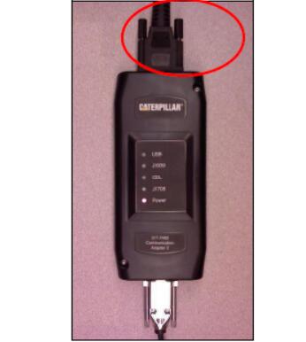
Step 1:Align and attach the DB25 connector end of the USB PC cable to the “PC cable” end connection on the Comm Adapter 3.
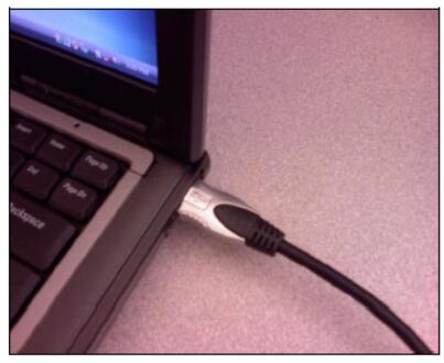
Step 2 Plug the USB Connector end of the PC cable into the USB port of the PC.
To connect the Comm Adapter 3 to the data link, perform the following steps:
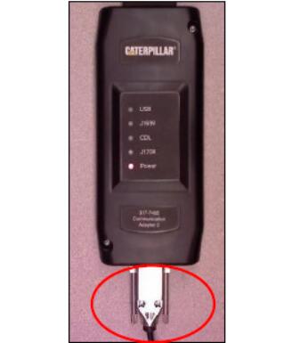
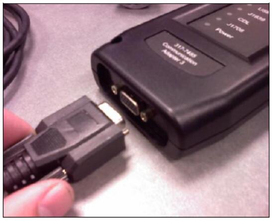
Step 1 After connecting the Comm Adapter 3 to the PC, connect the DB15- style connector end of the data link cable to the “Data Link” connection on the Comm Adapter 3.
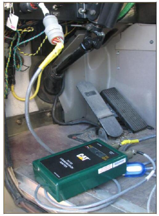
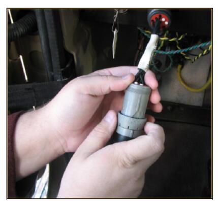
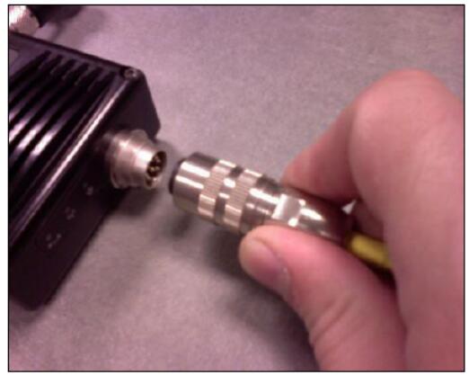
Step 2 Connect the other end of the data link cable to the service connector on the product
The lights on the front of the Comm Adapter 3 will glow and then will sequentially turn off from the top (“Data Link” end) to the bottom (“Computer” end) of the device. The Power LED will turn color from orange to red, and then the blue “USB” LED will blink once. The CA3 will not be operational until this sequence has occurred. The sequence can take up to 10 seconds. The service tool is now ready to be started the LED lights on the front of the device.
NOTE:The Power light on the Comm Adapter will glow if the data link is powered (machine power is on) or if the USB connector is plugged into the PC.
NOTE:For more information on the Comm Adapter 3, please refer to the Caterpillar Communications Adapter 3 Tool Operating Manual.
Configuring Cat Electronic Technician to use the Communication Adapter 3
In order for Cat Electronic Technician to work with the Communication Adapter 3, the settings must be changed to select the Communication Adapter 3 as the Communication Interface Device:
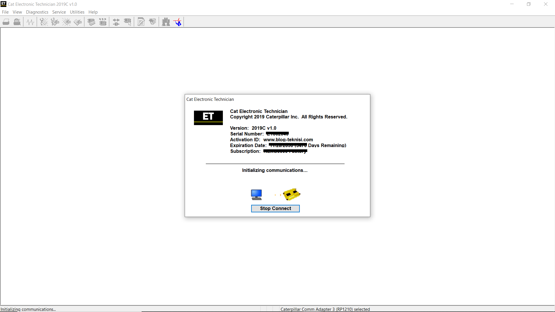
Step 1 Start Cat Electronic Technician.
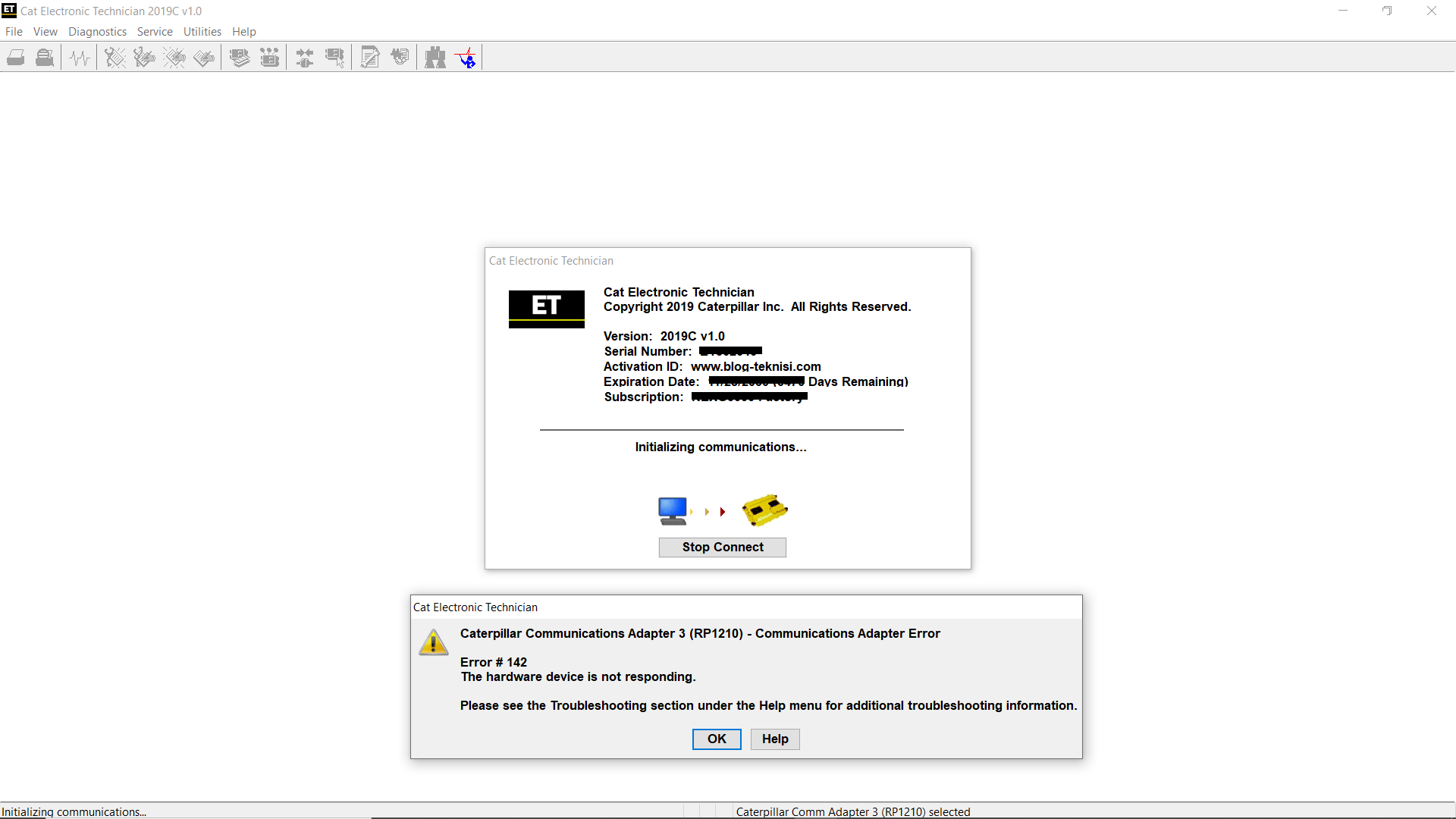
Step 2 Click the Stop Connect button when it appears.
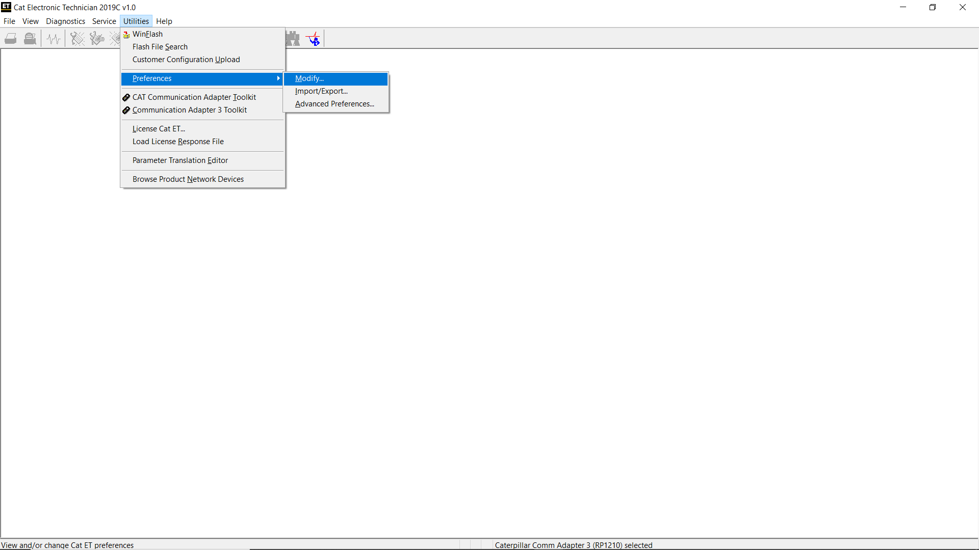
Step 3 Select the Utilities menu.
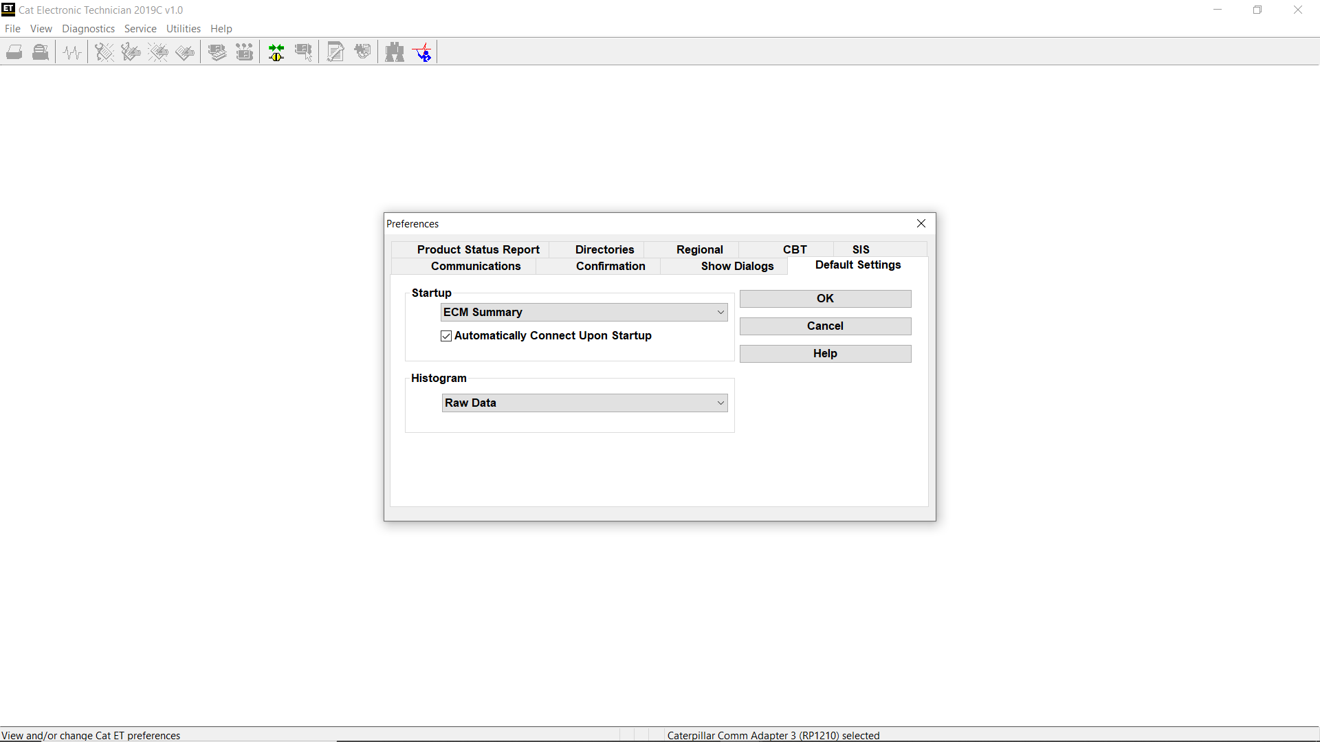
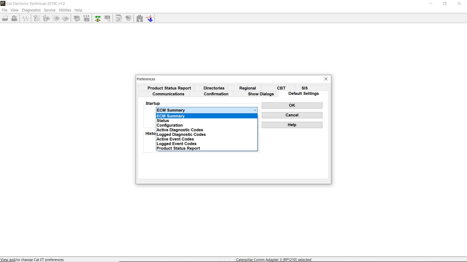
Step 4 Choose “Preferences…”
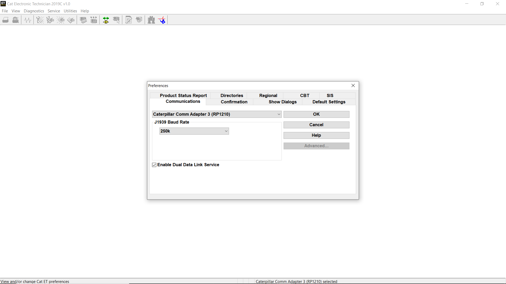
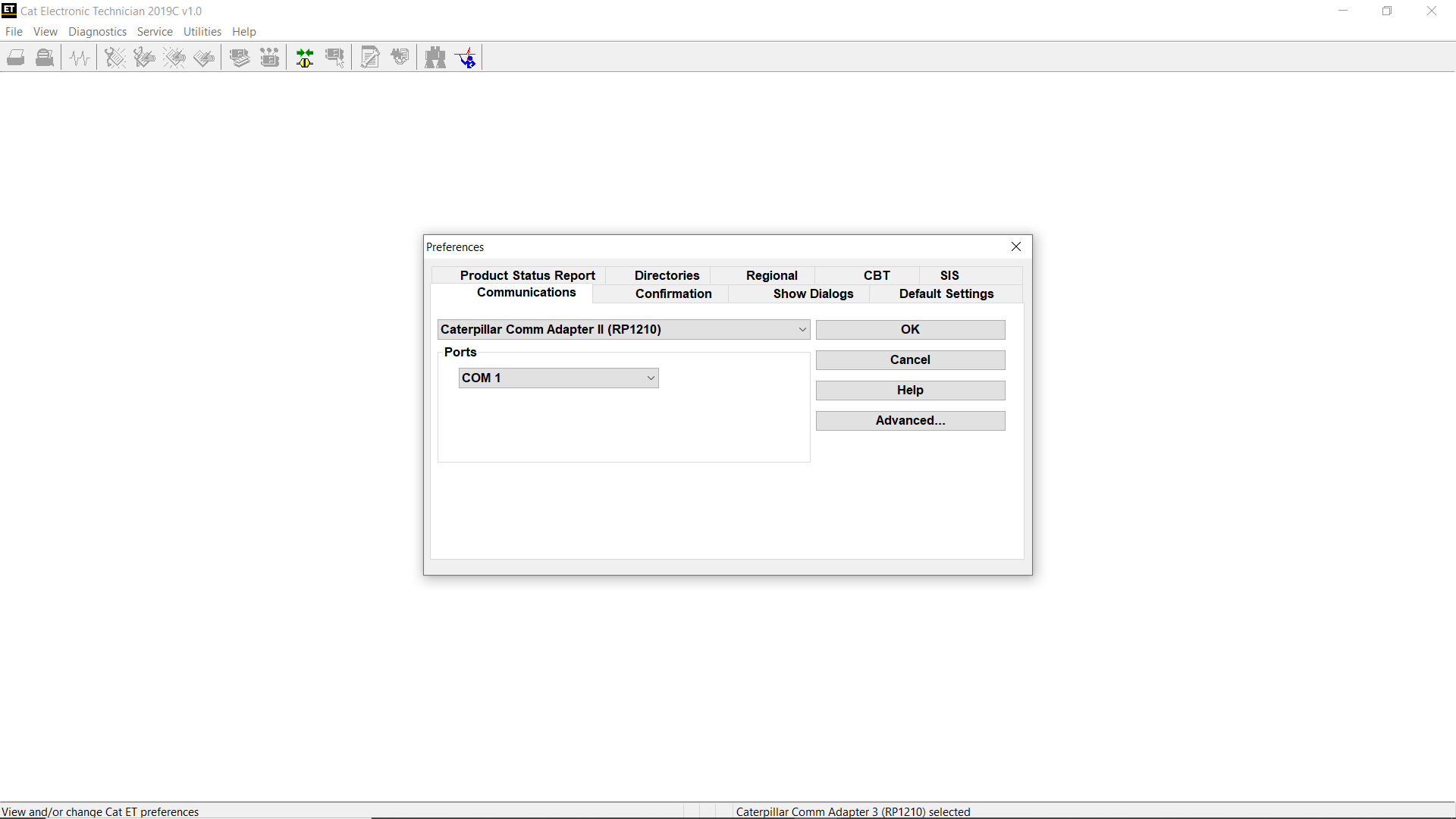
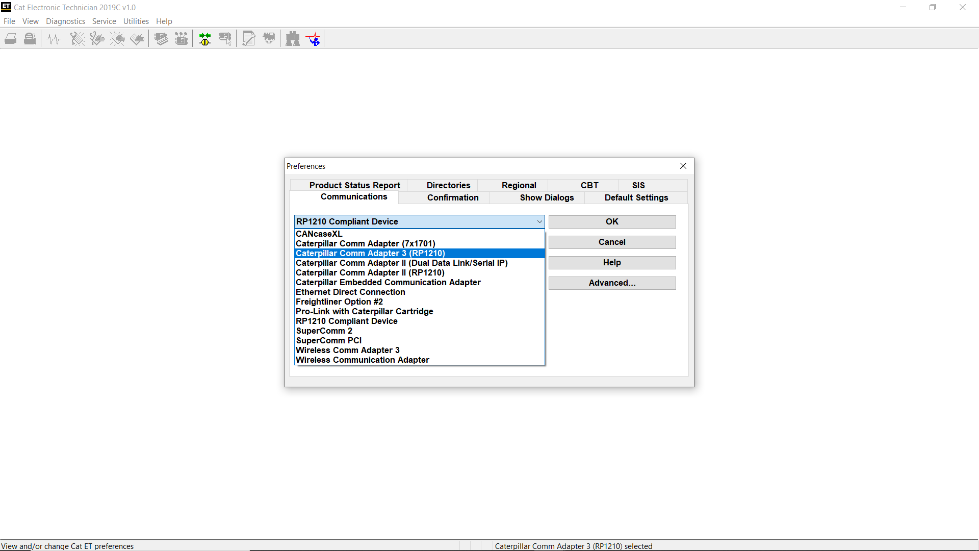
Step 5 Select the Communications tab.
Step 6 Select Cat Comm Adapter 3 (RP1210) and click OK.
NOTE: Because a growing number of products require multiple data link service, the “Enable Dual Datalink Service” checkbox has been pre-selected. Servicing ECMs on more than one data link requires this checkbox to be enabled. Failure to do this will result in undetected ECMs and reduced functionality.
Setting Up the Wireless CA3 (W-CA3) Radio
Requirements
317-7493 – Cat Wireless Communication Adapter 3 Radio
The following equipment is included in this group:
Description
Cat Communications Adapter 3
Cat 802.11 Wireless Radio
Wireless Radio CA3 Cable
Wireless Communication Adapter 3 CD-ROM
Wireless Communication Adapter 3 User’s Manual
NOTE: For specific part number information, contact the Parts Department of your local dealership.
To connect the Wireless CA3 Radio to the Comm Adapter 3, perform the following steps:
Step 1 Align and attach the round end of the Wireless CA3 Radio cable to the cable connection on the Wireless CA3 radio.
Step 2 Connect the other end of the cable to the cable connection on the Comm Adapter 3.
To connect the Communication Adapter 3 to the data link, perform the following steps:
Step 1 After connecting the Communication Adapter 3 to the Wireless CA3 Radio, connect one end of the data link cable to the data link connection on the Communication Adapter 3.
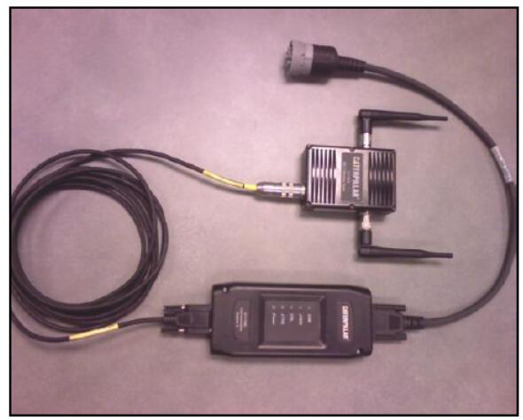
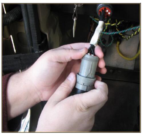
Step 2 Connect the other end of the data link cable to the service connector on the product.
If the data link is powered (machine power is on), the Power light on the Communication Adapter will glow and the diagnostic test will begin.
The lights on the front of the Communication Adapter 3 will sequentially glow from the top (“Data Link” end) to the bottom (“Computer” end) of the device. The service tool is now ready to be started.
Configuring Cat ET to use the Wireless CA3 Radio
In order for Electronic Technician to work with the Wireless CA3 Radio, the settings must be changed to select the Wireless Comm Adapter 3 as the Communication Interface Device:
Step 1 Start Cat Electronic Technician.
Step 2 Click the Stop Connect button when it appears.
Step 3 Select the Utilities menu.
Step 4 Choose “Preferences…”
Step 5 Select the Communications tab.
Step 6 Select Wireless Communication Adapter and click OK.
Setting Up the Cat Communication Adapter II
Requirements
171-4400 – Cat Communication Adapter II Group
NOTE:The 171-4400 Cat Communication Adapter II may be used; however, it is no longer available for purchase from Caterpillar Inc.
NOTE:For specific part number information, contact the Parts Department of your local dealership.
The following equipment is included in this group:
Requirements:
Description
Cat Communication Adapter II
Data Link Cable (24 inch)
This cable must be used for J1939/11 communications.
Serial PC Cable (25 foot)
Carrying Case
Block/Foam for carrying case
Communication Adapter II CD-ROM and User’s Manual
Optional Cables:
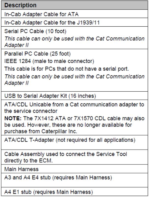
To connect the Communication Adapter II ( “Comm Adapter II”) to the PC, perform the following steps:
Step 1:Align and attach the DB25 connector end of the serial cable to the “PC
Cable” end of the Comm Adapter II.
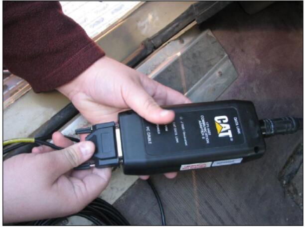
Step 2:Connect the other end (RS-232 end) of the serial cable to the communication port of the PC.
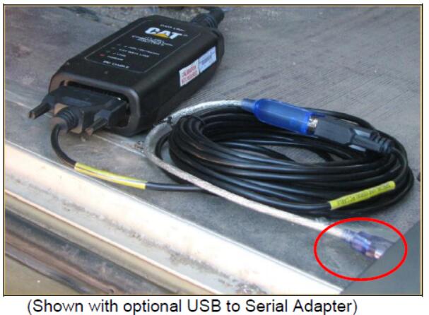
To connect the Communication Adapter II to the data link, perform the following steps:
Step 1 After connecting the Comm Adapter II to the PC, connect the DB15- style connector end of the data link cable to the “Data Link” end of the Comm Adapter II.
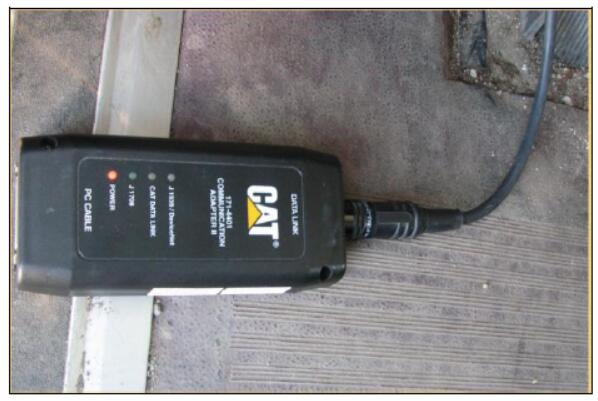
Step 2 Connect the other end of the data link cable to the product. If the data link is powered (machine power is on), the Power light on the Comm Adapter II will glow and the diagnostic test will begin. The lights on the front of the Comm Adapter II will sequentially glow from the top (“Data Link” end) to the bottom (“Computer” end) of the device. The service tool is now ready to be started.
Updating the Comm Adapter II Firmware to Serial IP
NOTE: Use the Comm Adapter II Toolkit version 4.0.12 or later to update the Comm Adapter II.
NOTE: Use the serial port only to upgrade the Communication Adapter II. Do not use the Parallel port.
To update the Comm Adapter II Firmware, perform the following steps:
Step 1 Make sure the Comm Adapter II is connected to the PC and the Power light is on.
Step 2 Go to the Start menu on the computer. Choose All Programs -> Caterpillar Comm Adapters -> Comm Adapter Toolkit.
Step 3 The Toolkit application will start up and display the Summary screen.
Step 4 Choose the Application Firmware Flash icon . Then click the
Select File button. The Select Firmware Flash File dialog box is displayed.
Step 5 The following files should be listed on the right:
ca2vi2.apf – application firmware
cav3i0.0 apf – application firmware
ca2v3i1.0.apf – SIP application firmware
Step 6 Highlight the ca2v3i1.0.apf file and click the OK button.
Step 7 Click the Begin Flash button to start the download.
Step 8 A dialog box showing the download progress will appear. The
download should take less than 45 seconds.
NOTE: All protocol lights on the front of the Comm Adapter II will blink while the firmware is flashed.
Step 9 When the download is complete, a dialog box will appear, allowing a return to the Toolkit Summary screen, a return to the Flash screen, or an Exit from the toolkit.
Step 10 Click the Exit button.
Configuring Cat ET to use the Communication Adapter II
In order for Electronic Technician to work with the Communication Adapter II, the settings must be changed to select the Comm Adapter II as the Communication Interface Device:
Step 1 Start Cat Electronic Technician.
Step 2 Click the Stop Connect button when it appears.
Step 3 Select the Utilities menu.
Step 4 Choose “Preferences…”
Step 5 Select the Communications tab.
Step 6 Change the Communication Interface Device to “Caterpillar Comm
Adapter II (Dual Data Link/Serial IP)” and click OK.
Step 7 Select the appropriate COM port (for example, “COM1”, “COM2”, etc).
This application firmware only supports Serial communications.
Setting Up the Cat Communication Adapter
Requirements
7X1700 – Cat Communication Adapter Group
NOTE: The 7X1701 Cat Communication Adapter may be used; however, it is no longer available for purchase from Caterpillar Inc.
NOTE:The 7X1701 Cat Communication Adapter does not support the J1939 data link.
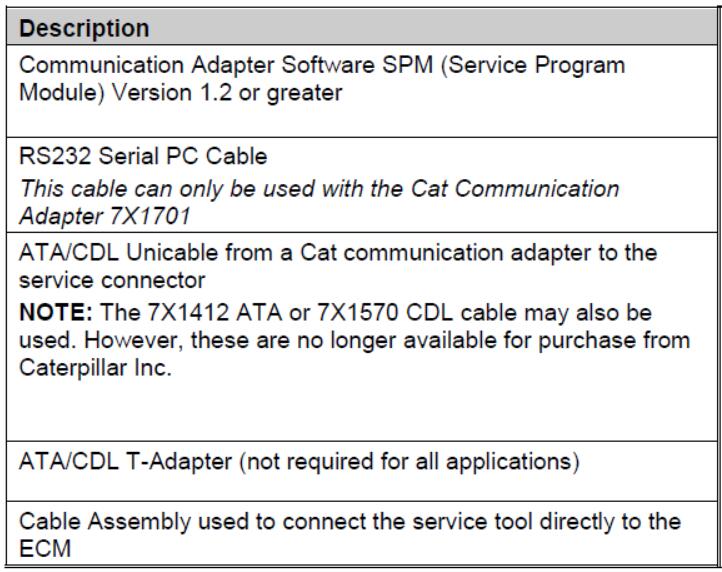
Other Requirements:
NOTE: For specific part number information, contact the Parts Department of your local dealership.
To connect the Communication Adapter (“Comm Adapter) to the PC, perform the following steps:
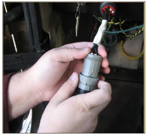
Step 1 Connect the 7X-1425 RS232 cable to an available Serial Port on the PC and to the Service Tool connector on the Communication Adapter.
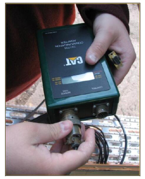
Step 2 Connect the 139-4166 Unicable to the control connector on the Communication Adapter and to the service connector on the product being serviced. The service tool is now ready to be started.